Subject Code&Title: EG7004 Soil Structure Engineering
Weighting: 50%
Learning outcomes assessed by this assignment: 2, 4, 5, 6, 7 and 8
EG7004 Soil Structure Engineering Assignment-East London University UK.

EG7004 Coursework Semester B 2020–21
Your coursework will comprise the development and analysis of a preliminary design for a support system for a deep braced excavation in granular soil
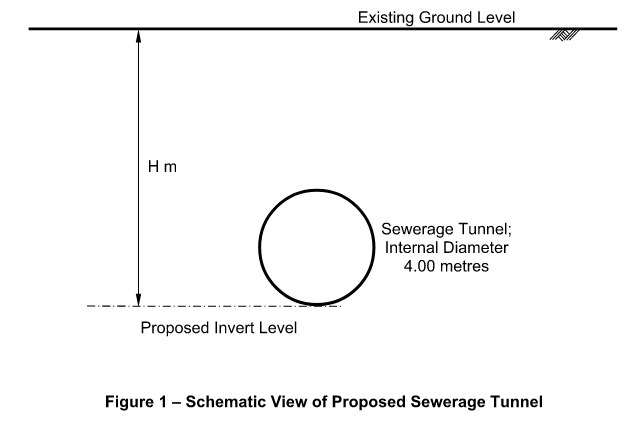
The excavation is for a cut and cover tunnel for a sewerage pumping scheme,as indicated in Figure 1. The scheme involves the installation of a 4 metre internal diameter circular culvert as shown which is going to be installed using a cut and cover technique.
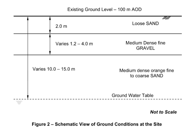
Ground investigation for the project has shown that the ground conditions
comprise layers of SAND and GRAVEL of varying thickness extending to a
depth of approximately 30 metres below existing ground level. The depth to
groundwater typically varies between 10.0 and 15.0 metres.
Typical Ground conditions are shown in Figure 2.
Each student is to design a slightly different section of the excavation, taking into account the variation in thickness of each soil layer and in soil strength parameters at different locations
The first thing that you will need to do in order to complete this coursework is to log on to the Moodle site for this Module and obtain the values of the
following for your specific design section:
The required depth of excavation
The thickness of each soil layer and its strength parameters
The depth to groundwater
These will be given in an Excel spreadsheet cross-referenced against your
student number.
Note that for construction purposes the excavation will need to extend to a
depth of 1.0 metres below the proposed tunnel invert level.
If you cannot find this information then you MUST contact Dr Walsh, the
Module leader, IMMEDIATELY.
Coursework Submission – Design Report
Your coursework submission will comprise a summary preliminary design
report and proposal for the support system for the excavation,
In developing your proposal two alternative design approaches are going to
be considered:
1.Design using the DPL Method as defined in CIRIA Report C517 (1999)
Temporary propping of deep excavation – guidance on design.
2.Design using Oasys FREW Software.
The excavation will be supported using AZ 32-750 Sheet piles to form the wall and props will comprise 273 mm diameter 10 mm wall thickness circular hollow section steel tubes. And as a first approximation you are to assume in your design that the depth of penetration of the wall below the base of the excavation will be equal to 10% of the overall depth of excavation
Your design report will include the following sections:
a) A description of the design that is being undertaken, the design
philosophy and the relevant input parameters to the design.
b) An outline design proposal for the support system based on the
recommendations of CIRIA Report C517 (1999) and justified in
accordance with the approach outlined in this document.
c) An analysis of the design loads for your proposed design as indicated by
the approach outlined in CIRIA C517
d) An analysis of the design loads for your proposed design based on a
moderately conservative assessment of ground conditions at the site using Oasys FREW software.
e) An analysis of the design loads for your proposed design based on a
worst case assessment of ground conditions at the site using Oasys
FREW software.
f) A critical comparison of the findings of the various analyses you have
carried out
g) General observations and design recommendations regarding your
original design proposal based on all of your findings here.
Notes on Coursework Submission:
As noted, your submission is to take the form of a design report
As such sections (b) to (e) should contain
- An explanation of all the assumptions that have been made in the design together with appropriate justification of these assumptions
- A summary of the key elements of the design, supported by drawings as necessary, sufficient that a Contractor could take the information provided and install the support system as designed
- A full summary of the expected performance of the support system, i.e. expected prop loads and any other relevant data obtained in the analyses e.g. maximum moments, expected wall deflections etc.
Given that the submission is to take the form of a design report, design
calculations should not in general be included in the main text of the report but should be contained in Appendices to the report. References to the
Appendices should then be made where appropriate in the main body of the report.
Where design calculations are presented as Appendices these should be
brief, relevant and to the point. MARKS WILL BE DEDUCTED for reports
which are “padded out” with unnecessary computer output or additional data related to calculations.
In preparing and submitting your coursework, please also note the following general guidance
- Final reports should be word processed in one and a half or double spaced Arial 12 point font.
- Where computer output is included, it is important that this is done in such a way that it is possible to check BOTH the INPUT to and OUTPUT values from the software.
- The Turnitin submission should comprise the text of the report only – it is not necessary to submit drawings or computer output to Turnitin.
ORDER This EG7004 Soil Structure Engineering Assignment NOW And Get Instant Discount