Unit Code :- Mace20041
Unit Title :- Hydraulics 2 Problem-Based Coursework
Weighting of the assignment: 15% of the unit assessment
This coursework includes:
Questions on Topic 1 (conservation laws) and Topic 2 (single pipeline systems only).
Mace20041 Hydraulics 2 Problem-Based Coursework – UK.
Question 1:-
Water flows through a vertical sluice gate in a rectangular channel as shown in Figure Q 1. The channel bed is horizontal upstream of the gate and has a 20° slope down stream of it. The channel width is 4 m. The elevation of a point C at the intersection between the upstream water surface and the sluice gate is 1.10 m from the bottom of the channel (see Figure Q1).
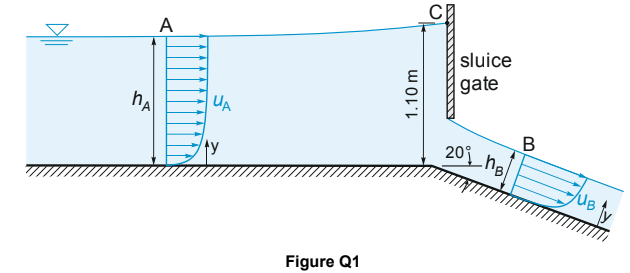
The velocity profiles at sections A and B are described by the following equations,respectively:
where y is the distance from the channel bottom, u A,S and u B,S are respectively the surface velocities at sections A and B, and h A = 1 m and hB = 0.35 m are the respective water depths.
(a) Assuming that Bernoulli’s equation is applicable along a surface streamline between section A and the sluice gate, estimate the surface velocity uA,S at section A.
(b) Find the surface velocity uB,S at section B.
Mace20041 Hydraulics 2 Problem-Based Coursework – UK.
(c) Neglecting friction forces between sections A and B, and assuming that the pressure distribution is hydrostatic at both sections, determine the drag force on the sluice gate.
Question 2 :-
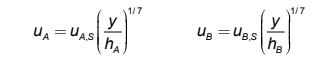
Water flows through a converging pipe as shown in Figure Q2. A U-tube manometer containing a fluid with specific gravity 1.87 is installed to measure the difference between the Pitot pressures at points 1 and 2. The difference between the static pressures at the same points is p 1 – p 2 = 1500 Pa. Assuming incompressible flow and uniform cross-sectional velocity profiles, determine:
(a) the pressure loss due to viscous effects between points 1 and 2;
(b) the flow rate in L s–1
(c) If the Pitot tube at point 1 is replaced with a piezo meter, what would be the difference in column heights in the U-tube manometer? (i.e. what would be the new value of h in Figure Q2?)
Question 3 :
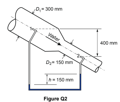
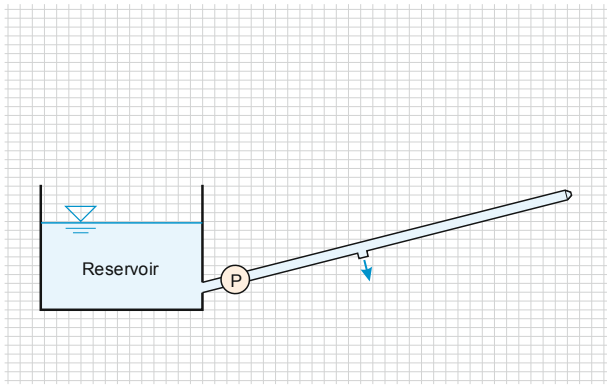
Water is pumped from a reservoir through a pipeline discharging to atmosphere as illustrated in Figure Q3. The water level in the reservoir is constant and equal to 10 m (Above Ordnance Datum) whereas the elevation of the pipe centreline at the outlet B is 12 m. The pipeline is made of two segments, AJ and JB. Both segments have length 50 m and diameter 150 mm. The pipeline terminates at B with a nozzle, with outlet diameter 75 mm.
A pump (P) installed along pipe AJ supplies a continuous discharge of 40 L s–1, while a constant discharge of 20 L s
–1 is extracted at the junction J. The friction factor of pipe A J for the prescribed discharge is 1 = 0.03.
Mace20041 Hydraulics 2 Problem-Based Coursework – UK.
Calculate:
(a) the velocities in pipes AJ and JB;
(b) the head loss due to friction along pipe AJ.
Assuming that pipe JB has roughness ks = 0.3 mm, and neglecting minor losses,
(c) calculate the head loss along pipe JB;
(d) determine the head developed by the pump P;
(e) sketch the qualitative behaviour of the energy and hydraulic grade lines along the pipeline AB (including the terminal nozzle). For convenience, Figure Q3 is reproduced on a square grid in Appendix A (on page 5), on which the grade lines can be sketched.
(f) For an alternative scenario where the discharge extracted at J is zero and the pump head is 6.5 m, determine the discharge in the pipe AB assuming a uniform roughness ks = 0.3 mm.
You may use this sheet to sketch the qualitative behaviour of the energy and hydraulic grade lines in your answer to Question 3(e).
Read More :-
ENG742s1 P24344 Control Systems Coursework 2 – Portsmouth University UK.

